Capacitance
Objectives
In this chapter we will learn
What is capacitance.
Calculate capacitance of some simple geometries.
Methods of connecting capacitors in series and parallel.
Calculate energy stored in a capacitor.
Understand behavior of an insulator (dielectric) placed in plates of a capacitor.
Gauss’ law in the presence of dielectrics.
Capacitance
Consider two conducting spheres of radius r and R such that r < R.
When both the spheres touch each other what will be the potential difference between the two?
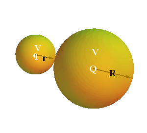
If the electric potential value is V, what will be the charge on each sphere?
Electric potential V on a conducting sphere of radius R is related to the charge Q on the sphere.

As per above equation, the charge Q on the bigger sphere is
![]()
Similarly charge q on the smaller sphere is
![]()
Since r<R, therefore q<Q.
Although both the spheres are at same electric potential but the charge stored in bigger sphere is more than the charge stored in smaller sphere.
We can say that the charge storing capacity of small sphere is less than that of bigger sphere.
Charge storing capacity of a conductor is called capacitance.
Capacitance of a sphere of radius R is defined as
![]()
If we store Q charge on any conductor and potential on the surface is V, the capacitance C of such a conductor or a device is defined as

In other words, capacitance is the amount of charge a conductor store to raise its potential by a unit Volt.
Capacitance is only the function of geometry (in this case radius) of the conductor or device.
SI Units for capacitance will be Coulomb/Volt or ![]() or Farad.
or Farad.
General Definition of a Capacitor
Any conductor is a capacitor but in general two conductors, isolated electrically from each other and from their surroundings, are used as capacitor.
For a single conductor, other conductor is considered as if it is placed at infinity.
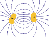
When the capacitor is charged, the charges on each conductor has the same magnitude q but opposite signs.
Parallel Plate Capacitor
A more conventional arrangement, called a parallel - plate capacitor, consisting of two parallel conducting plates of area A separated by a distance d.
When a capacitor is charged, its plates have charges of equal magnitudes but opposite signs: +q and -q.
However, we refer to the charge of a capacitor as being q, the absolute value of these charges on the plates.
q is not the net charge on the capacitor.

Potential difference ΔV between the plates is historically written as V.
Charging of a Capacitor
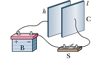
One way to charge a capacitor is to place it in an electric circuit with a battery.
A battery is a device (charge pump) which maintains a constant potential difference V on its two terminals.
These are indicated by two unequal parallel lines. Longer line is at higher potential and shorter line is at lower potential.
 |
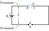 |
When switch S is closed, electric field in battery derives electron from the negative terminal to plate ℓ of the capacitor.
Positive terminal removes equal number of electrons from plate h of the capacitor.
All the charge movement stops once the potential difference between the capacitor plates equals the potential difference between the battery terminals.
Checkpoint 1
Does the capacitance C of a capacitor increase, decrease, or remain the same (a) when the charge q on it is doubled and (b) when the potential difference V across it is tripled?
Answer :
Hint: Capacitance of the capacitor only depends on its shape (geometry). It will not change by total charge on it or the potential difference across the plates.
Calculating the Capacitance
Recipe for calculating capacitance:
We need to find out ratio of charge and potential difference.
First assume that plates have charge +q and -q.
Now compute potential difference V for this charge using following steps.
Use Gauss' law  , to determine electric field
 ![]() between the plates.
between the plates.
Determine potential difference V between the plates using equation  , along any path from negative to positive plate (Choose a convenient straight line).
The capacitance C is given by equation
![]()
Capacitance of a Parallel Plate Capacitor
Let us assume that the plates of our parallel - plate capacitor are so large and so close together that we take electric field ![]() to be constant throughout the region between the plates (neglect the fringing of the electric field at the edges).
to be constant throughout the region between the plates (neglect the fringing of the electric field at the edges).
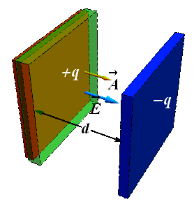 |
Draw a Gaussian surface (Transparent green box) enclosing the positive (red) plate.
Electric field is finite only on inner Gaussian surface, on all other five surfaces (four sides and one inside the conductor) electric field is zero. As per Gauss' law
Electric field ![]() on the inner surface is constant therefore net flux Φ through Gaussian surface is
on the inner surface is constant therefore net flux Φ through Gaussian surface is

As per Gauss' law
![]()
Once electric field is known we can calculate potential difference V between the plates by integrating over any path
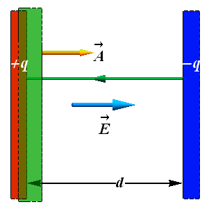

Let us choose a straight path of integration (green path in figure) from negative plate to positive plate

By substituting the value of E, we get

For a parallel plate capacitor, the capacitance will be given as

In capacitors, the units for permittivity constant ![]() are Farad/m
are Farad/m
![]()
![]()
Capacitance of a Cylindrical Capacitor
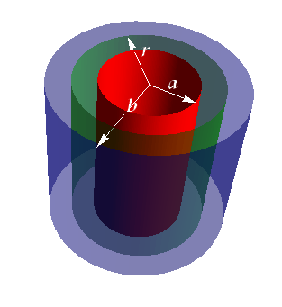
Consider a cylindrical capacitor of length L formed by two coaxial cylinders of radii a and b.
We assume that b<<L. Again neglecting the fringe effects at the edges, we assume electric field ![]() between the two plates to be constant.
between the two plates to be constant.
 |
 |
Draw a Gaussian cylindrical surface (green) of radius r enclosing the inner cylinder. Since ![]() is constant so we can write total flux as
is constant so we can write total flux as

Only curved surface is contributing, on sides of the cylinder electric field is zero. As per Gauss' law

Surface area of the Gaussian cylinder is A=(2π r)L.
Once electric field is known we can calculate potential difference V between the plates by integrating our any path

Let us choose a straight path of integration from negative plate to positive plate (green path).

When we are making a positive displacement d s from negative plate to positive plate, the radius is reducing, therefore d s = -d r.
By substituting the value of E we Get.


Here also capacitance of cylinder only depends on the geometrical factors.
Capacitance of a Spherical Capacitor
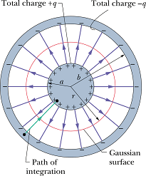
Consider two concentric spheres of radius a and b with a<b.
Draw a Gaussian spherical surface of radius r enclosing the inner sphere. Since ![]() is constant so we can write total flux as
is constant so we can write total flux as

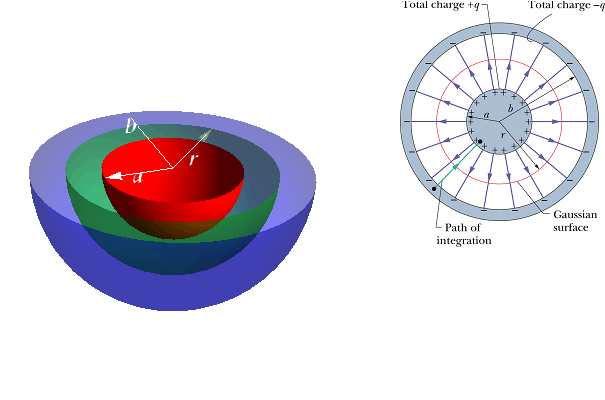
As per Gauss' law

Surface area of the Gaussian sphere is ![]() .
.
Once electric field is known we can calculate potential difference V between the plates by integrating our any path

When we are making a positive displacement ds from negative plate to positive plate, the radius is reducing, therefore d s = -d r.
By substituting the value of E we get.


Capacitance of a Isolated Sphere
![]()
If the radius of outer shell becomes infinity b→∞ and we substitute inner shell radius a=R. we get capacitance of an isolated charge sphere of radius R.
![]()
This is the same value what we calculated in the beginning of the chapter.
Checkpoint 2
For capacitors charged by the same battery, does the charge stored by the capacitor increase, decrease, or remain the same in each of the following situations? (a) The plate separation of a parallel-plate capacitor is increased. (b) The radius of the inner cylinder of a cylindrical capacitor is increased. (c) The radius of the outer spherical shell of a spherical capacitor is increased.
Answer :
Hint: If the electric potential difference across the capacitor remains constant the charge will change directly with change in capacitance.
![]()
Problem - 1 (Spherical Capacitor)
The plates of a spherical capacitor have radii 38.0 mm and 40.0 mm. (a) Calculate the capacitance. (b) What must be the plate area of a parallel-plate capacitor with the same plate separation and capacitance?
(a) Capacitance of a spherical capacitor is a function of the inner radius a and outer shell radius b

![]()
(b) Capacitance of a parallel plate capacitor is a function of the area A of the plate and plate separation d.

The separation between the two sphere is d = (b-a).
![]()
![]()
![]()
Connecting Capacitors in series and parallel.
When there is a combination of capacitors in a circuit as shown in figure (a).
We can replace this combination with an equivalent capacitor as shown in figure (b).
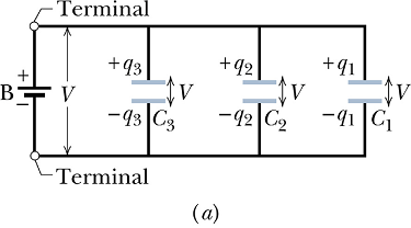 |
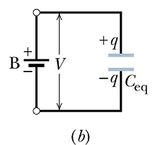 |
Equivalent capacitor is a single capacitor that has the same capacitance as the actual combination of capacitors.
Capacitors in parallel
Combination shown below is a combination in which capacitors are connected to the battery in parallel.
When a potential difference V is applied across several capacitors connected in parallel, that potential difference V is same across each capacitor.
The total charge q stored on the capacitors is the sum of the charges stored on all the capacitors.
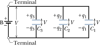
If we look at each capacitor in above parallel combination, we can write
![]()
The total charge on the parallel combination is
![]()
The equivalent capacitance, with same charge q and applied potential difference V as the parallel combination is
![]()
If there are n number of capacitors connected in parallel, the equivalent capacitance can be written as

Capacitors in Series
Consider a combination in which capacitors are connected in series to the battery.
When a potential difference V is applied across several capacitors connected in series, the capacitors have identical charge q.
The sum of the potential differences across all the capacitors is equal to the applied potential difference V.
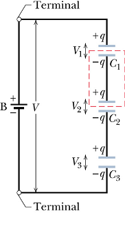
Let us understand why, in series combination, all the capacitors have same charge q
When battery is connected it will only charge the plates connected to it. The lower plate of 3rd capacitor will get - q charge.
Equal amount of electrons will get repelled from the upper plate of 3rd capacitor's lower to the lower plate of 2nd capacitor.
Now equal amount of electrons will get repelled from the upper plate of 2nd capacitor to lower plate of 1st capacitor. This will bring +q charge on the upper plate of 1st capacitor as the electrons will be attracted by positive terminal of battery.
Once we know charge on each capacitor, we can calculate potential difference across each capacitor
![]()
Now the total potential difference V due to battery is equal to the sum of these three potential differences.

The equivalent capacitance, with same charge q and applied potential difference V as the series combination is


If there are n number of capacitors connected in series, the equivalent capacitance can be written as

Checkpoint 3
A battery of potential V stores charge q on a combination of two identical capacitors. What are the potential difference across and the charge on either capacitor if the capacitors are (a) in parallel and (b) in series?
Answer :
Hint: (a) In parallel, total charge is sum of the charges on two individual capacitors. Potential difference on both will be same as both are connected to the battery terminals.
![]()
(b) In series combination total charge is the charge on individual capacitor but the total potential difference is the sum of potential difference across each capacitor.
![]()
More Complex Capacitor Combination
In general a capacitor system may consists of smaller capacitor groups, that can be identified as connected "in parallel" or "in series".
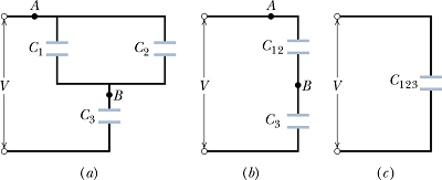
This example shows such kind of complex combination.
Look at figure (a) from point A to point B. This part can be treated as a parallel combination of ![]() and
and ![]() . If we take its equivalent capacitor to be
. If we take its equivalent capacitor to be ![]() , the circuit can be redrawn as in figure (b)
, the circuit can be redrawn as in figure (b)
Value of ![]() can be computed as
can be computed as
![]()
Now in circuit (b), capacitor ![]() and
and ![]() form a series combination, equivalent capacitor
form a series combination, equivalent capacitor ![]() of this combination can be computed as
of this combination can be computed as

By substituting the value of ![]() we can get total equivalent capacitor
we can get total equivalent capacitor ![]() , of this complex combination.
, of this complex combination.

Problem - 2 (Neither parallel nor series)
Capacitor 1, with C1 = 3.55 μF, is charged to a potential difference V0 = 6.30 V, using a 6.30 V battery. The battery is then removed, and the capacitor is connected to an uncharged capacitor 2, with C2 = 8.95 μF (as shown in the Figure). When switch S is closed, charge flows between the capacitors. Find the charge on each capacitor when equilibrium is reached.
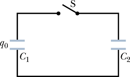
This is a case where capacitors are not connected to any battery, or charging source. We can neither treat it a parallel system nor a series combination.
When capacitor 1 was charged, the charge ![]() on it can be calculated from its capacity
on it can be calculated from its capacity ![]() and the applied potential difference by battery
and the applied potential difference by battery ![]() .
.
![]()
Once it is disconnected from the battery, the charge remains on it and when it is connected to the other capacitor, charge redistribute itself to make the potential difference across both the capacitors same. Let us assume the equilibrium potential difference is V.
Let us consider after redistribution of charge, ![]() is the charge on capacitor
is the charge on capacitor ![]() and
and ![]() is the charge on capacitor
is the charge on capacitor ![]() . Now as per conservation of charge
. Now as per conservation of charge
![]()
Since potential difference across both the capacitors is same v, so we can write

We can rewrite total charge as
![]()
![]()
Once the value of V is known we can calculate ![]() and
and ![]() .
.


Energy Stored in a Capacitor
To charge a capacitor, battery moves away electron from positive plate and puts it on negative plate.
Let us assume that battery is moving charge in installments of -dq from positive plate to negative plate.
At any given moment, assume that each plate has charge q and ΔV=0-V' is the potential difference between two plates.
The work done by battery (it is opposite to work done by electric field) in moving charge -dq will be
![]()
C is the capacity of the capacitor. Total work done by battery in moving total charge Q from one plate to other can be computed as below.

This work is stored in the capacitor as potential energy.

We can rewrite the energy stored in a capacitor as

The potential energy of a charged capacitor is also viewed as the energy stored in the electric field between its plates.
Graphical Method
When we charge a capacitor let us see how the potential difference across its plate changes?
Potential difference ![]() across the plates of a capacitor C, changes with the charge q as shown in the graph below.
across the plates of a capacitor C, changes with the charge q as shown in the graph below.
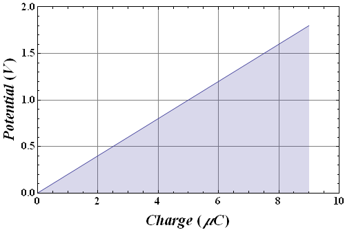

This shows that energy stored in a capacitor is equal to the area under the curve in this plot.
In a charge versus potential plot of a capacitor, the energy stored in the capacitor is equal to the area under the curve.
Energy Density
Another quantity Energy density u, is defined as the potential energy per unit volume.
Volume of a parallel plate capacitor is
![]()
Potential energy stored in the capacitor 
Energy density u will be

Now if we substitute the capacity![]() of the parallel plate in above equation, we get
of the parallel plate in above equation, we get

Electric field between the parallel plate capacitor is E=V/d. By substituting the value of E, we get

Although this relation is derived for a parallel - plate capacitor, it holds in general.
If ![]() is the electric field at any point in space, the energy density at that point is
is the electric field at any point in space, the energy density at that point is  .
.
Problem - 3 (Energy Density)
A charged isolated metal sphere of diameter 18 cm has a potential of 7000 V relative to V = 0 at infinity. Calculate the energy density in the electric field near the surface of the sphere.
Potential on the surface of a charged sphere is given by equation
![]()
Electric field on the surface of a charged sphere is given by equation

From these two equations we get the value of E in terms of V and R as

Energy density u at any point is given as


Capacitor with a Dielectric
Let us do an experiment (simulation) which was done by Michael Faraday in 1837.
Connect a battery (with constant voltage) to the plates of a capacitor.
We will monitor charge on one of the plates (blue) with an electrometer.
What happens if we insert a dielectric (insulator) between the plates?
We saw that the charge increases. Look at the equation of the capacitor.
![]()
When V is constant, the charge q can increase only with increase in capacitance C.
Let us do another experiment
Take a charged capacitor with constant charge q on its plates.
Connect a potentiometer to measure electric potential difference V.
What happens if we insert a dielectric (insulator) between the plates?
![]()
For constant charge q , electric potential difference V can decrease, only with increase in capacitance C.
With insertion of a dielectric between the plates, the capacitance increases by a factor κ, known as dielectric constant of the insulating material. New value of C is
![]()
The capacitance, only depends on the geometry of the capacitor?
![]()
Here L represents the geometrical factor, like in parallel plates, L= A/d, in spherical capacitor L=4π a b/(b-a).
With dielectric, new capacitance should be written as
![]()
This is only possible if we replace the constant ![]() in a dielectric with
in a dielectric with ![]() .
.
In a region completely filled by a dielectric material of dielectric constant κ, in all electrostatic equations the permittivity constant ![]() is replaced by
is replaced by ![]() .
.
Electric field due to a point charge q at a distance r in a dielectric medium of dielectric constant κ is given as

Outside an isolated conductor
![]()
The potential difference V due to a point charge q at a distance r in a dielectric medium is

Problem-4
A parallel - plate air - filled capacitor has a capacitance of 75 pF. If the region between the plates is now filled with material having κ = 6.3, what is the capacitance?
The capacitance of a capacitor with dielectric constant κ is related to the air filled capacitance as
![]()
Dielectrics: An Atomic View
What happens when a dielectric (insulator) is placed in an electric field?
There are two kind of dielectric materials, polar and non polar.
The polar materials are made up of dipoles like water ![]() ) molecules.
) molecules.
Non polar materials are made up of just neutral atoms/molecules without any charge separation.
Non - polar
Let us see what happen when these neutral (non-polar) molecules are placed inside an electric field![]() .
.
Change the field magnitude with the slider.
The electrons experience force ![]() and nucleus experience force
and nucleus experience force ![]() .
.
This cause deformation of the electron cloud and separation of charges.
This process makes the molecules an induced dipoles.
Polar
Dielectrics and Gauss' Law
If the charge exists in vacuum (air is considered as vacuum as its dielectric constant is almost one) the Gauss's law applied to the following surface will be given as
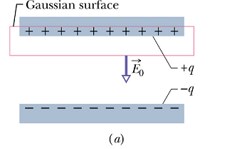

![]()
Fill the space between the plates with an insulator of dielectric constant κ.
Apply the Gauss' law to the same surface, now the total charge enclosed contains an additional charge q' on the surface of the dielectric.
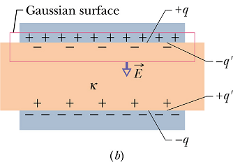


Now the obtained electric field E is weaker than the original electric field ![]() in vacuum.
in vacuum.
Let us assume that the original electric field ![]() got weaker by a factor κ.
got weaker by a factor κ.

Comparing above two equations giving the value of E, we get

Gauss Law in a dielectric medium is written as

By substituting the value of q-q' with q/κ, the Gauss' law in a dielectric is written as

Points to be noted:
The flux integral now involves ![]() , not just
, not just ![]() .
.
Use dielectric constant κ and ignore enclosed induced charge q', consider only enclosed free charge q in the Gaussian surface.
κ is the property of a dielectric, it might be constant or might be function of position (inhomogeneous medium) over entire Gaussian surface.
If κ is not constant or is a function of position, it is kept inside the integral.